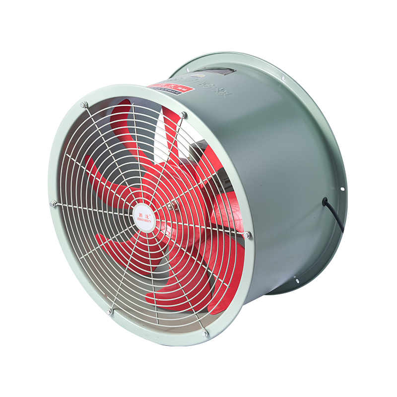
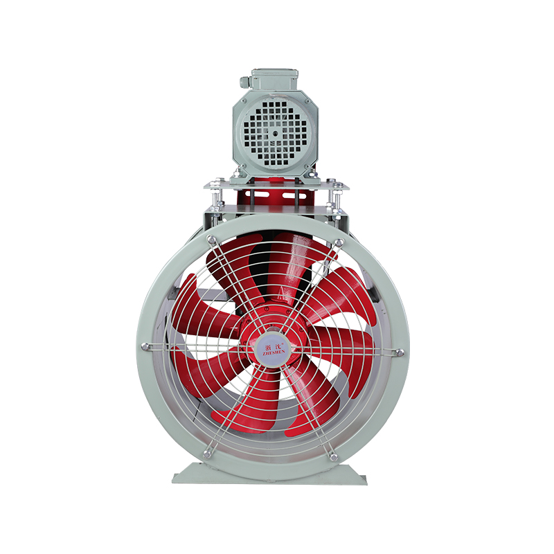
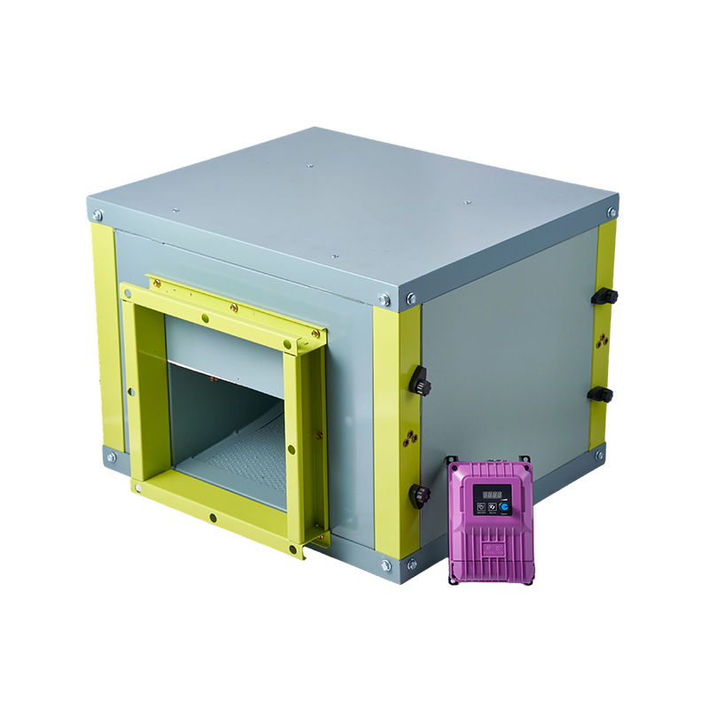
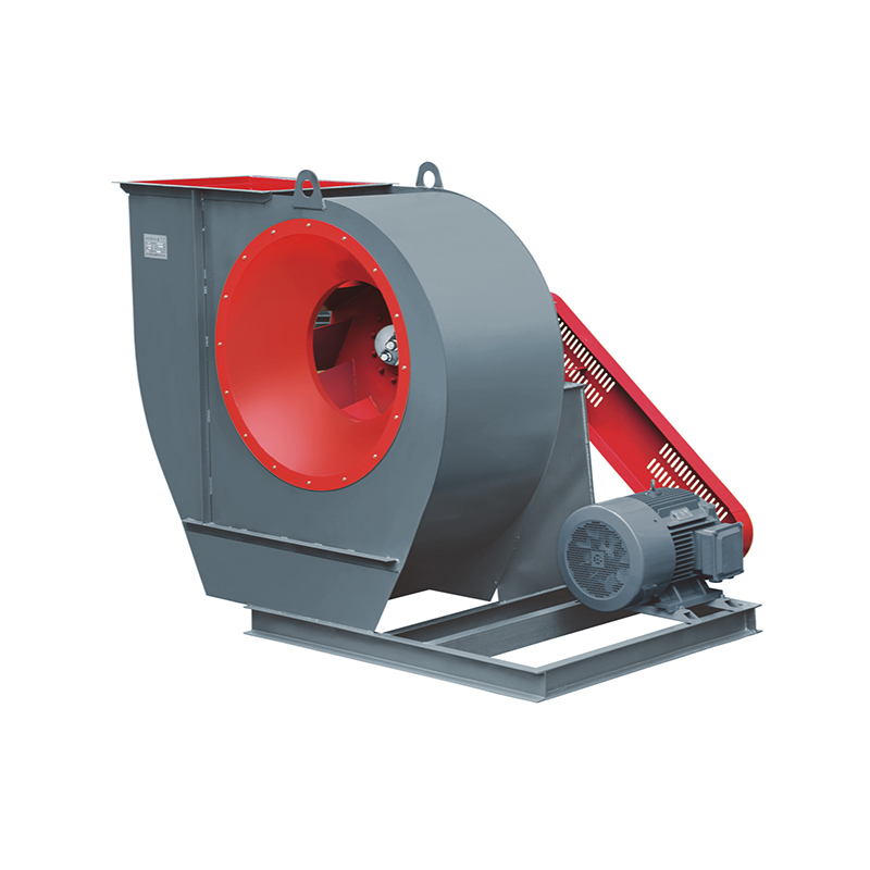
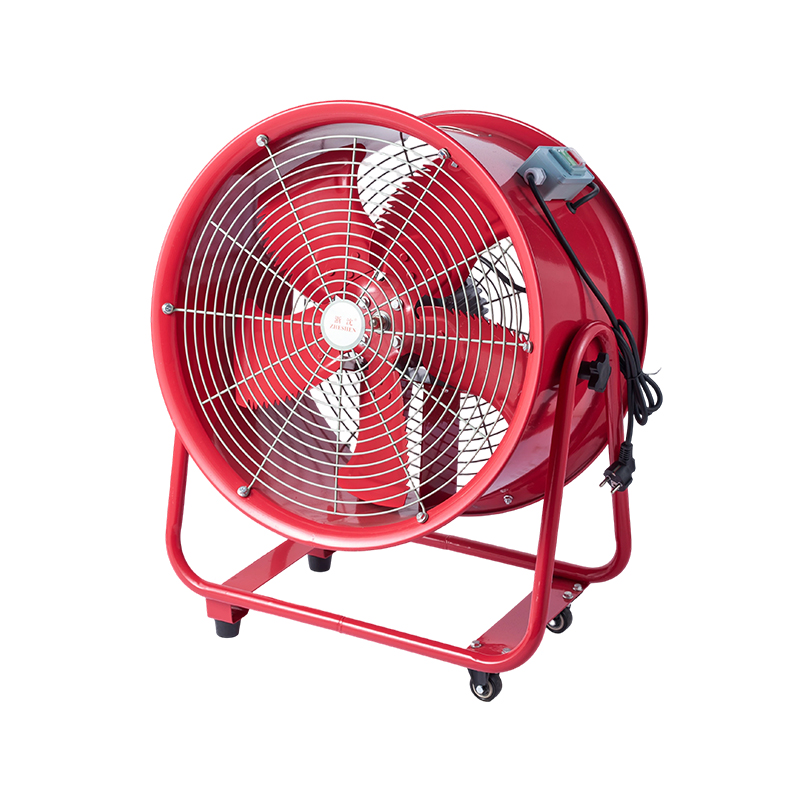
The T35-11, BT35, and FT35 series axial flow fans serve as replacements for the 30K4 series. The T35...
+ VIEW MOREIndustry News

Industrial ventilation in hazardous areas depends on moving a sufficient volume of air against the resistance created by ducts, louvers, filters and the room itself. Airflow describes how much air the fan can deliver; static pressure describes how much resistance it can overcome while doing so. Selecting equipment by a single free-air airflow figure often leads to under-performance once the fan is installed in a real system. An Explosion Proof Axial Fan must therefore be chosen with both quantities in view, together with the hazardous-area classification and the physical constraints of the installation.
Airflow rate is the volume of air that passes through the fan in a given period. The value required for a space depends on the volume of the room, the number of air changes needed for the process, the heat or contaminant load and any applicable safety guidance. An initial estimate based on room volume and desired air-change rate provides a starting point; it is then refined by the actual purpose of the ventilation—general dilution, local extraction or temperature control.
Room dimensions yield a gross volume. Multiplying that volume by a target air-change rate produces a first airflow figure. That figure is checked against the real sources of heat or contaminant, the way supply and extract air are distributed, and any regulatory or company standards that apply. Providing these details to a supplier allows the discussion of fan size to begin from the actual duty rather than from a generic catalogue page.
Catalogue airflow is frequently stated for free delivery or for a low resistance. Once the fan is connected to ducts, grilles, dampers or weather louvers, the system imposes a pressure drop. The operating airflow then falls below the free-air value. A fan that appears adequate on paper may therefore deliver less air than the design requires unless the system resistance is taken into account at the selection stage.
Static pressure is the portion of fan pressure that is available to overcome friction and restrictions in the air path. It is distinct from airflow: a fan may move a large volume of air when resistance is low, yet deliver far less once ducts and fittings are added. When the installation includes any significant length of duct, filters or directional changes, static pressure capability becomes as important as the airflow rating.
Long runs, reduced cross-sections, elbows, transitions and terminal devices all dissipate pressure. Two plants that install the same fan model can obtain different airflows if one uses short, straight duct and the other uses a tortuous route with several restrictions. Calculating or estimating these losses, and then selecting a fan whose performance curve covers the resulting duty point, reduces the risk of shortfall after commissioning.
A fan that discharges directly through a wall faces mainly the resistance of its own casing, a weather louver and any guard. A ducted installation adds the friction of the duct and every fitting. Even a direct wall mounting needs clear inlet and outlet zones; obstruction close to the fan can still raise the effective resistance and cut the delivered airflow. Confirming the intended arrangement—wall, roof or ducted—before selection keeps the pressure requirement realistic.
A fan performance curve shows how airflow declines as the pressure the fan must develop rises. The system resistance curve shows how pressure loss increases with airflow for a particular duct arrangement. The intersection of the two curves is the operating point. Selecting a fan only by its maximum airflow, without reference to the pressure at which that airflow occurs, often places the real operating point far from the intended duty.
When the system resistance exceeds what the fan can develop at the required airflow, the delivered volume falls. Air movement at the far end of a duct may become weak, design air-change rates may not be met, and local extraction points may fail to capture contaminant. Before replacing the fan, the actual duct layout and the published performance data are checked to confirm that the shortfall is caused by pressure limitation rather than by another fault.
A fan with a higher free-air airflow does not automatically solve a high-resistance system. The larger unit may still operate at a point where its pressure development is inadequate, or it may introduce unwanted noise, higher power demand or mechanical incompatibility with the existing opening. Matching the fan's curve to the calculated system resistance remains the more reliable approach.
The ventilation purpose, the size of the space and the operating conditions define the target airflow. That target, together with a description of the air path, forms the basis for comparing candidate fans. An Explosion Proof Axial Fan is then shortlisted only among models whose performance data cover the expected duty.
System pressure losses are estimated or measured and are compared with the fan's published curve. The airflow that corresponds to that pressure—not the free-air maximum—is the value used for final selection. Technical documentation for the specific model is reviewed with the supplier so that the operating point is understood before the order is placed.
Airflow and pressure address only the ventilation duty. The hazardous-area classification, the nature of any flammable gas or dust, the required protection markings, ambient temperature limits and the available electrical supply must all match the fan's certified configuration. Selection is incomplete until these site conditions are confirmed.
Mounting orientation, clearances at inlet and outlet, duct connection dimensions and the ability to reach the fan for inspection all affect whether the selected unit can be installed and maintained as intended. Drawings or clear descriptions of the location help avoid mechanical clashes and inaccessible equipment after the fan arrives on site.
A single high airflow figure without accompanying pressure data does not define a working duty. The same figure can correspond to very different system behaviours depending on resistance.
Omitting elbows, reductions, filters or louvers from the resistance estimate produces an optimistic airflow prediction. The shortfall appears only after installation, when correction is more costly.
A fan that meets the airflow and pressure requirement but lacks the correct explosion-protection rating cannot be used in the classified zone. Protection suitability is verified independently of aerodynamic performance.
Airflow at the operating point, static pressure, performance curve reference, mounting dimensions, electrical ratings, ambient limits and explosion-protection markings form the minimum set of data that should be agreed before purchase.
| Parameter | Role in Fan Selection | Information to Confirm |
|---|---|---|
| Required airflow | Sets the volume of air the system must move | Room volume, air-change target, process load |
| System static pressure | Determines resistance the fan must overcome | Duct length, fittings, louvers, filters |
| Operating point on fan curve | Intersection of fan capability and system resistance | Performance data at the expected pressure |
| Installation arrangement | Influences both pressure loss and mechanical fit | Wall, ducted or roof; clearances; connection sizes |
| Explosion-protection rating | Ensures suitability for the hazardous area | Zone or division, gas or dust group, temperature class |
| Electrical and ambient limits | Matches supply and environment | Voltage, frequency, ambient temperature range |
Airflow and static pressure together define whether an axial fan will deliver the intended ventilation once it is installed. Catalogue free-air figures are only a starting point; duct resistance, the shape of the performance curve and the hazardous-area requirements complete the picture. Zhejiang Shenli Explosion proof Electromechanical Co., Ltd. manufactures explosion-proof axial fans for industrial ventilation duties. Review of required airflow, estimated system pressure, installation layout and site classification against available fan performance data and protection ratings supports selection of a unit matched to the actual operating conditions.
The T35-11, BT35, and FT35 series axial flow fans serve as replacements for the 30K4 series. The T35...
+ VIEW MORE
The Model T40 axial-flow fan is suitable for general ventilation and air exchange in factories, ware...
+ VIEW MORE
The T35-11, BT35, and FT35 series permanent magnet variable-frequency axial-flow fans serve as repla...
+ VIEW MORE
The air cabinet features a clean and elegant exterior design; all components of the cabinet body are...
+ VIEW MORE
The Model 4-72C centrifugal ventilator is designed to convey air and other gases that are non-flamma...
+ VIEW MORE
The CTF Mobile Low-Noise Axial Flow Fan represents a new generation of low-noise ventilation equipme...
+ VIEW MORE
Copyright ©
Zhejiang Shenli Explosion proof Electromechanical Co., Ltd.
All rights reserved