
 English
 中文简体
 Français
The T35-11, BT35, and FT35 series axial flow fans serve as replacements for the 30K4 series. The T35...
+ VIEW MORE
What Makes an Axial Fan Exhaust System Suitable for Industrial Ventilation
Deliver multiple validated explosion-proof fan solutions
Industrial buildings require continuous exchange of indoor air to limit heat build-up, remove stale air and maintain workable conditions for people and processes. Stagnant zones, elevated temperatures and the accumulation of process emissions create the need for reliable exhaust capacity. Axial fans move air parallel to the axis of rotation and are frequently examined for applications that demand substantial volume flow against modest system resistance. An Axial Fan Exhaust arrangement that matches the building's airflow target, static-pressure demand and installation constraints can form a practical part of a general ventilation scheme.
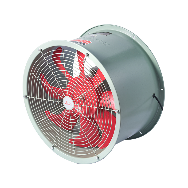
Operating Principle of Axial Exhaust Arrangements
Generation of Airflow Along the Fan Axis
Rotating blades impart momentum to the air so that it travels in the same direction as the shaft. Air enters at the inlet side, passes through the impeller and leaves at the discharge side. Because the flow path is relatively direct, axial designs are often considered when the system resistance remains low and the primary requirement is volume rather than high pressure.
Contribution of Impeller Geometry and Drive Motor
Blade shape, pitch and diameter influence the volume of air moved and the pressure that can be developed. The motor supplies the torque needed to keep the impeller at the design speed under the expected load. Matching motor power, speed and duty rating to the impeller and to the actual system resistance keeps the fan operating within its intended range.
Orientation and Overall Air-Path Layout
Installation direction decides whether the unit extracts air from the space or supplies outdoor air into it. Effective exhaust depends on the presence of adequately sized replacement-air paths so that extracted air is continuously replaced. Coordination of inlet openings, exhaust points and internal obstacles determines how evenly air moves through the building.
Attributes That Support Industrial Ventilation Duties
Capacity for Moving Large Air Volumes
In low-resistance systems an axial impeller can deliver the high volume flow needed to dilute heat or dilute general contaminants in large rooms. The required capacity is calculated from room volume, desired air-change rate and any process heat load rather than from the highest figure listed on a data sheet.
Straightforward Construction and Installation Flexibility
A compact, relatively simple housing allows mounting in wall openings or at the end of short duct runs when the product configuration permits. Available structural openings and clearance around the fan influence which physical size and mounting style can be used.
Matched Motor and Impeller Performance
Stable operation requires that motor power, impeller diameter and rotational speed remain consistent with one another and with the system curve. Reliance on a single nominal airflow figure without reference to the accompanying pressure can lead to selection of a unit that fails to deliver the expected volume once installed.
Accessibility for Inspection and Cleaning
Components that can be reached without extensive dismantling simplify routine checks of blade condition, fastener tightness, motor temperature and vibration. Scheduled cleaning of the impeller and inlet area prevents the gradual loss of airflow that accompanies dirt build-up.
Typical Industrial Settings for Axial Exhaust Fans
Production Workshops and Manufacturing Areas
Heat and general process air can be extracted from open workshop spaces when the system resistance remains within the fan's capability. Ventilation rates are set according to the heat released by machinery and the nature of the operations performed.
Warehouses and Storage Buildings
Large floor areas and high ceilings benefit from planned air exchange. Building length, internal racking and the location of inlet openings affect how uniformly air is drawn toward the exhaust points.
Plant Rooms and Utility Spaces
Localized heat from electrical or mechanical equipment can be removed by a correctly sized axial exhaust fan, provided ambient temperature and any airborne contaminants remain inside the limits stated for the unit.
Agricultural and General Industrial Structures
Dust, humidity and mild corrosives influence material selection and enclosure ratings. The fan must be confirmed suitable for the specific atmosphere before it is installed.
Performance Variables That Guide Selection
Required Volume Flow and Air-Exchange Targets
Room volume, occupancy, process heat and the desired number of air changes determine the airflow the fan must supply. Selection proceeds from these calculated needs rather than from the largest published capacity.
Static Pressure Imposed by the System
Ducts, louvers, filters and guards add resistance that the fan must overcome. Axial fans lose volume rapidly as resistance rises; the published performance curve is therefore examined at the expected operating pressure.
Electrical Supply and Motor Ratings
Voltage, frequency, current draw and rated power must match the site supply and the continuous duty required. Motor protection and any starting method are confirmed against local electrical practice.
Noise, Vibration and Running Stability
Impeller balance, mounting stiffness and unobstructed airflow paths keep noise and vibration within acceptable workplace limits. Installation that follows the manufacturer's guidance and subsequent periodic inspection help maintain that stability.
Installation Practices That Preserve Intended Performance
Location of Exhaust Openings Relative to Air Inlets
Exhaust points are placed where warm or contaminated air tends to collect, while replacement air is admitted at locations that encourage cross-flow through the occupied zone. Short-circuiting between adjacent inlet and outlet openings is avoided.
Direct Wall Mounting Versus Ducted Arrangements
Wall mounting keeps system resistance low. Connection to ductwork increases resistance in proportion to length, bends and fittings; only configurations approved for the chosen fan are used.
Mechanical Fixing and Electrical Connection
Secure mounting, correctly rated cabling and appropriate protective devices form the basic installation standard. Guards remain in place and access for later inspection is preserved.
Maintenance Actions That Sustain Airflow Over Time
Cleaning and Visual Inspection
Accumulated dust on blades and in the inlet reduces delivered volume. Isolation of the electrical supply precedes any cleaning or inspection of the impeller, housing, guards and fasteners.
Motor and Bearing Condition
Unusual noise, elevated temperature or increased vibration signals the need for closer examination. Lubrication and bearing service follow the intervals and methods given in the product documentation.
Diagnosis of Reduced Performance
Blocked inlets, reversed rotation, higher-than-expected system resistance or damaged components are checked against the fan's rated operating point before parts are replaced.
Selection Sequence for a Specific Facility
The primary ventilation objective—general air exchange, heat removal or another defined task—is established first. Building dimensions, heat sources and environmental conditions are recorded. Rated airflow, pressure capability, motor data, physical dimensions and noise figures are compared with those requirements. Performance under the expected system resistance is confirmed from the published curve. Datasheets, installation instructions and available support are reviewed so that the chosen unit can be integrated and maintained without uncertainty.
Overview of Selection and Operating Considerations
| Consideration | Influence on Ventilation Result | Verification Step |
|---|---|---|
| Airflow capacity | Determines air-exchange rate in the space | Calculate from volume and process load |
| System static pressure | Affects actual delivered volume | Read performance curve at expected resistance |
| Motor and electrical match | Ensures continuous operation on site supply | Confirm voltage, frequency and protection |
| Installation layout | Controls distribution and avoids short-circuiting | Coordinate inlets, outlets and internal obstacles |
| Maintenance access | Preserves long-term airflow | Plan cleaning and inspection intervals |
| Environmental suitability | Prevents premature deterioration | Match materials and enclosure to atmosphere |
Matching Fan Characteristics to Industrial Ventilation Needs
Airflow volume, system resistance, motor configuration, installation layout and ongoing maintenance together decide whether an axial exhaust arrangement will meet the ventilation target. Axial designs warrant evaluation when the duty is high volume against relatively low resistance. Zhejiang Shenli Explosion proof Electromechanical Co., Ltd. produces axial exhaust fans for industrial ventilation applications. Review of available airflow and pressure ratings, motor options, mounting arrangements and environmental suitability against the specific building requirements allows selection of a configuration that supports consistent air exchange.
Related Product
-
-
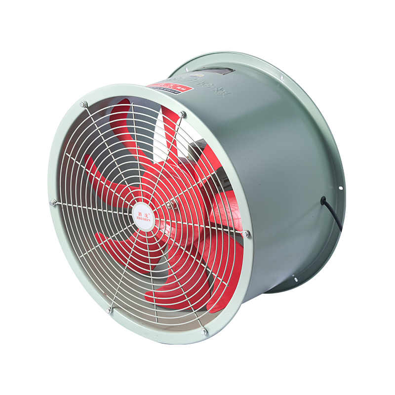
The T35-11, BT35, and FT35 series permanent magnet variable-frequency axial-flow fans serve as repla...
+ VIEW MORE -
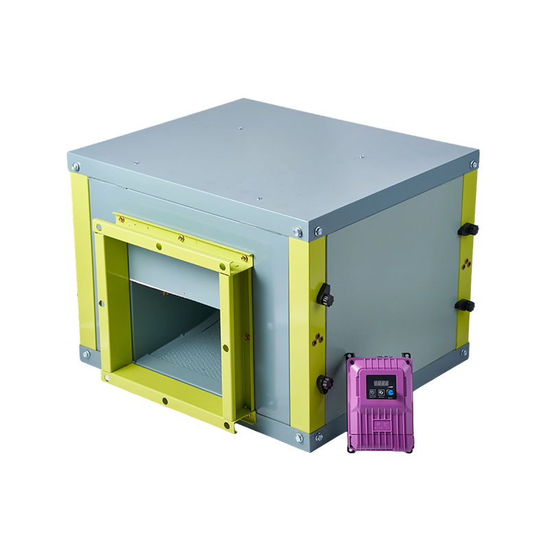
The air cabinet features a clean and elegant exterior design; all components of the cabinet body are...
+ VIEW MORE -
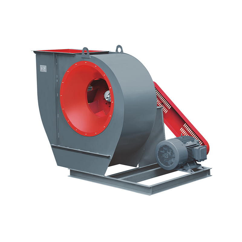
The Model 4-72C centrifugal ventilator is designed to convey air and other gases that are non-flamma...
+ VIEW MORE -
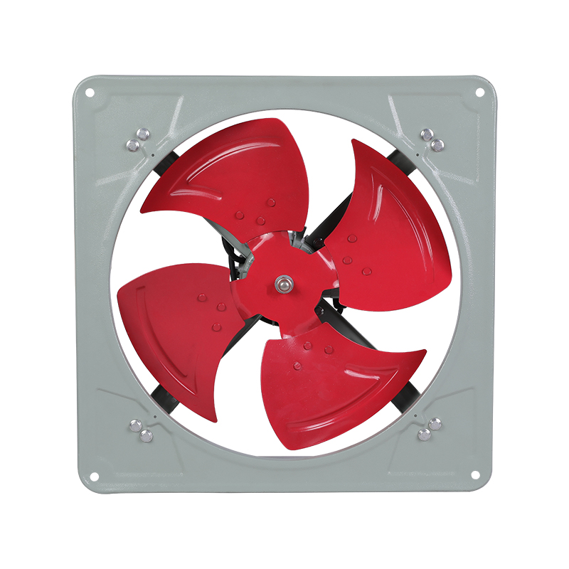
The FA-B series uses single-phase, capacitor-run axial-flow exhaust fans. The FTA series runs on thr...
+ VIEW MORE -
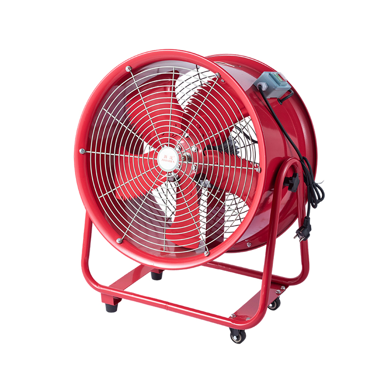
The CTF Mobile Low-Noise Axial Flow Fan represents a new generation of low-noise ventilation equipme...
+ VIEW MORE
Do you have questions? Do not wait, Let's talk!
Products:
Contact Us
- Tel/Whatsapp:+86-13586259916
- Tel:+86-15825511111
- Email: [email protected]
- Add:Jin'ao Industrial Zone, Shanshi, Daxi Town, Wenling City, Zhejiang Province
Mobile
Copyright ©
Zhejiang Shenli Explosion proof Electromechanical Co., Ltd.
All rights reserved

